|
CONSTRUCTION
STORY OF
SCRATCHBUILT
STREET ROD
|
 |
Building Period: 30 March 1999 - 30 June 1999
PART 11
MISCALLANEOUS AND DASHBOARD
If you remember, the front shock
absorbers
were held in place by temporary nuts made from plastic wire isolation.
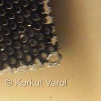
It was time to manufacture real nuts. The material was a 0.6 mm thick,
perforated aluminium sheet. This was once the grille of a cassette tape
recorder. One of the holes were enlarged to 1 mm and then threaded with
M 1.2 mm threading tool. Then the nut was freed from the sheet with the
aid of X-acto #11 blade.
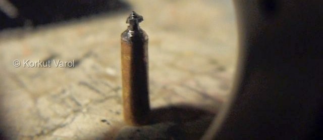
Here you see the union of the nut with the shock absorber.
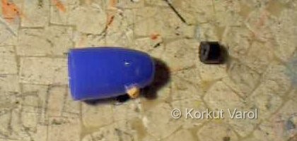
For the front headlamps, the rear cap
of a ball-point pen seemed very suitable. Other contributors were a
wheel
retainer that was cut to fitting profile with the cap and a toothpick
piece,
to hold the assembly better. The toothpick was inserted in the
cap,
only about 1 mm protruding. The reason is, this headlamp will be placed
right over the shock absorber and its center hole will house the nut.
This
configuration will also help in partly disguising the upper resting
bracket
of the front suspension. At
the right is the headlamp body assembly.
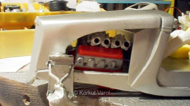
The boomerang-shaped cutout of the
hood
blocked the first exhaust port, so its profile was changed. A big-block
Chevy engine is used to power this rod. The cylinder head and
carburettors
are from Corvette Grand Sport, by Accurate Miniatures.
For the custom dashboard, a rosewood grained cardboard was used.

The base of the dashboard was carved from 4-mm thick balsa.

The gauges were computer-generated and printed on paper.

This is the three items' assembly.
Scotch
tape was applied over the gauges before the assembly, to imitate the
shine
of glass over the gauges.

Next, the shelf panel was made from
brass
sheet and stuck to the backside of the dashboard with CA glue. It was
painted
matt black after this pic was taken.

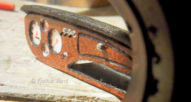
Holes 0.5 mm. dia. were drilled for
the
rocker switches and the ignition key. Silver dots were applied for
imitating
the bezels. Copper wire 0.2 mm dia. was painted silver and inserted
through
the holes till it protruded 2 mm from the dashboard. The excess lengths
were cut at the back, and the wires were secured by CA glue.
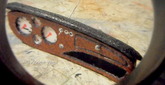
Dots of CA glue were applied at the
tips
of the switches and painted gloss black. Ignition key was from Detail
Master.
The glovebox handle is a pin inserted and excess part cut away.
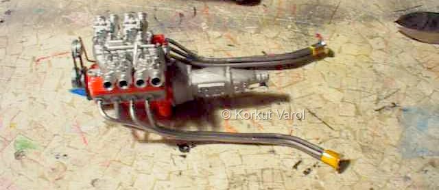
The engine in temporary assembly with
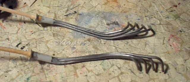
the exhaust pipes. The exhaust pipes are made from 1.5 mm diameter
solder
wire, glued together with 5-minute epoxy. The tips are cut from
velocity
stacks of a 1/20 McLaren, and drilled for realistic looks.
The transition from the pipes to the tips are made by applying putty and sanding down to shape.
 .......................