|
CONSTRUCTION
STORY OF
SCRATCHBUILT
STREET ROD
|
 |
Building Period: 30 March 1999 - 30 June 1999
PART 12
STEERING LINKS, PAINTING AND INTERIOR
Now to the steering links. The items
shown
here are the bellcrank to transfer the fore-and-aft motion of
the
rod from the steering box to right and left, pushing the track rods.
The
item on the right is the pivoting bracket of the bellcrank mechanism.
All
are made from 0.2 mm brass sheet. Note the four pop-ups made by
hammering
a point that resemble bolt heads when painted.
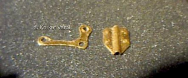
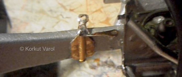
A pin is soldered to the bellcrank. Its length is cut so that the pivoting bracket will just fit in.

The two are assembled on the chassis
with
glueing the bracket on the chassis, taking care that no glue touches
the
pin, so that it will rotate freely.
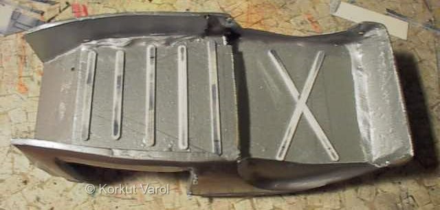
Back to the body. Srips from styrene
sheet
are cut and given oval profile at the ends and glued with CA glue under
the floor panels. These represent the reinforcing stampings on the
panel.
The rear axle is united with the
brake
discs taken from the New Beetle. The wheel retainers are put in the
hubs
before assembling with 5-minute epoxy.

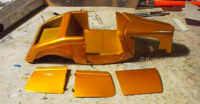
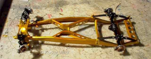
The body and chassis are painted at last. Clear amber glass paint was airbrushed for 5 coats.
The rear axle assembly is put on the
chassis,
with pins cut to proper length in the spring eyes and fastened with CA
glue to prevent slipping off.
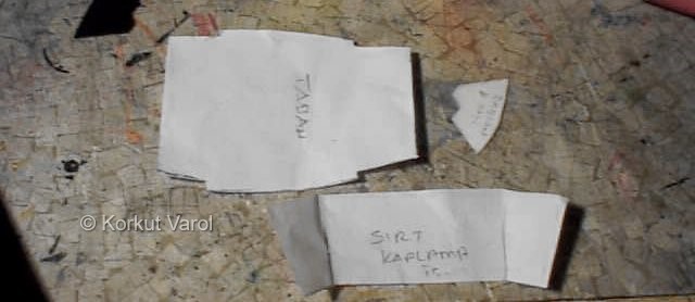
Templates for trim elements are traced on to paper from the body itself.
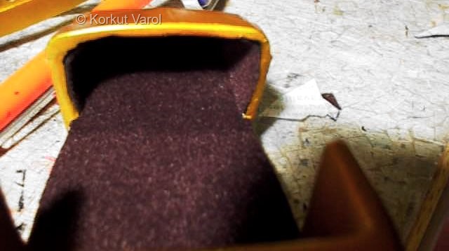
The floor and side kick panels are
covered
with self-adhesive black velvet sheet, cut in accordance with the
templates.
 .....................