 |
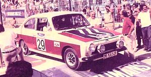
34 KA 501 Renç Koçibey's Car |
 |
 |
|
|
34 KA 501 Renç Koçibey's Car |
|
|
Scale
: 1/24
Started:
1 December 2010
Finished: 23 February 2011
Page 2 of 3
|
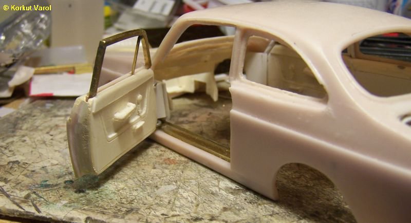
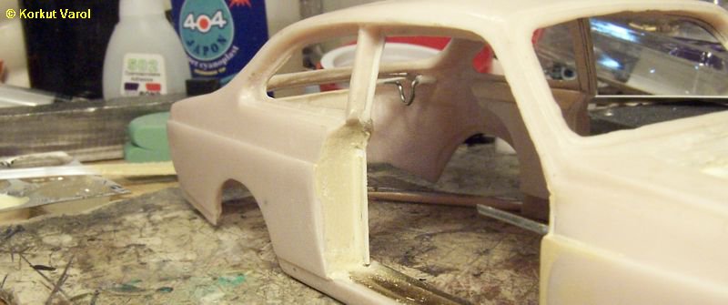
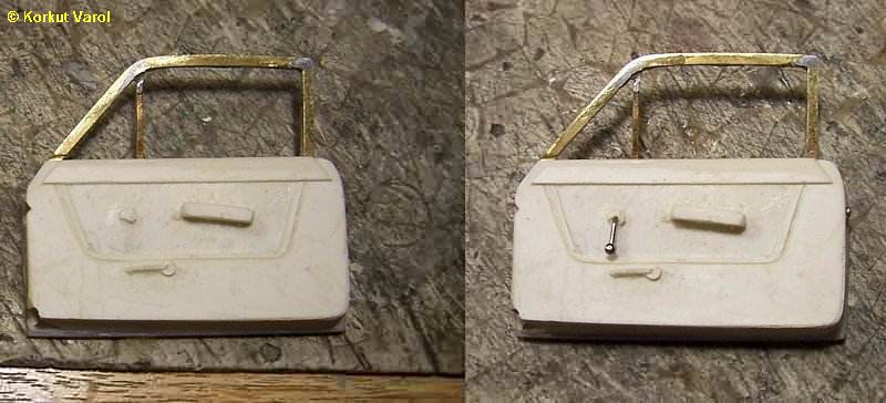
I filled the space between outer
and inner door panels with polyester putty and made a pre-sanding.
|
|
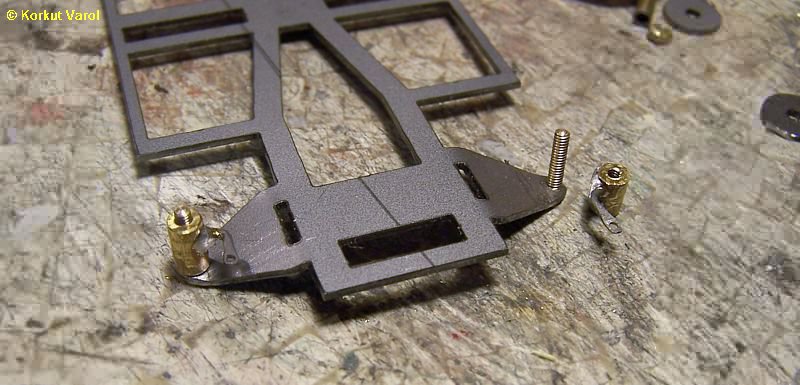
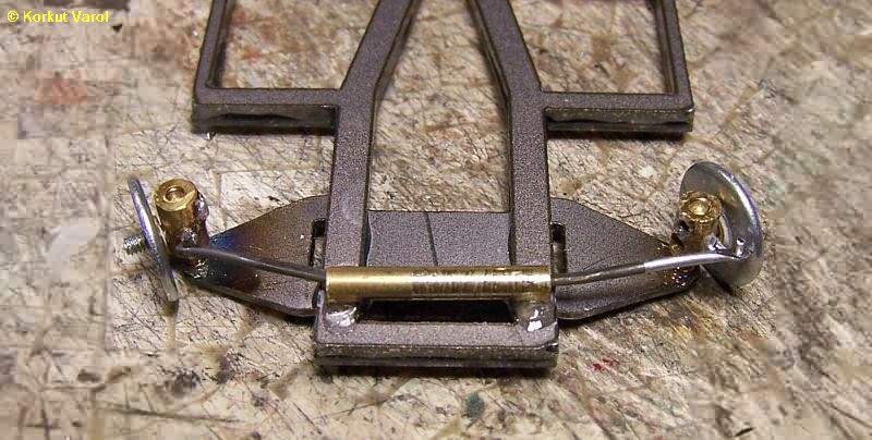
I
had the chassis cut in 3 pieces with a laser cutter, from steel sheet.
I wanted to make a poseable front end. To achieve this, I drilled and
tapped the ends of the wishbones with M2 thread. I cut the heads of two
M2 screws and installed in place, gluing with superglue to prevent
rotation. I prepared the "kingpins" from a 4 mm dia. brass rod, by
drilling and tapping with M2 thread. I also tapped M2 threads to hold
the axle pin. I prepared the steering arms from 1.2 mm steel wire,
flattening and drilling 1 mm hole at one end. Then I bent the wire and
inserted one end to the kingpin, then fixed by soldering.
 |
|
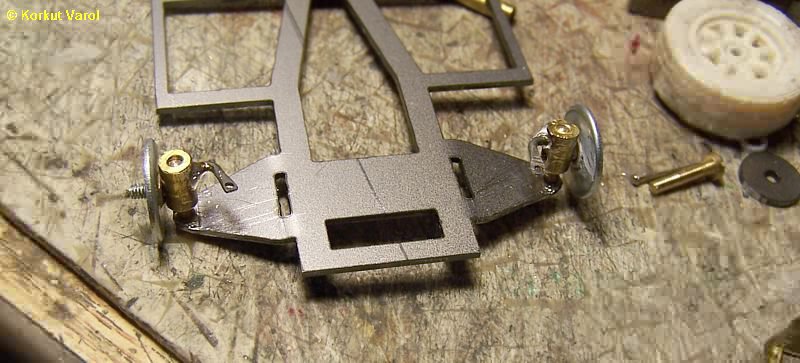
I
inserted M2 nuts inside 5/32" washers and glued them with superglue
(brake discs). Then I screwed the brake discs on the M2 axles and made
ready for wheel mounting. Later, a tie rod will be manufactured.
 |
|
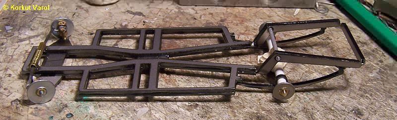
The
steering arms did not prove to have proper steering geometry, so I
dismantled them and made a new set. I also made the tie rod from 1.2 mm
steel wire and made a brass tube housing. I fixed this housing to the
chassis with epoxy glue.
|
|
21
January 2011:
I
made and assembled the rear axle group. I cast the differential over a
4 mm styrene tube, then inserted the axle through the eyes of laser-cut
rear springs and fixed with superglue. Then I made a brass bar with M2
threads at both ends. I prepared the "rear drum surfaces" by inserting
M2 nuts inside M4 washers and screwed them on the threaded axle. I
fixed the assembly to the chassis with epoxy glue.
|
|
Using the wheel from a Ford Escort kit, and a suitable tyre, I made a smaller offset wheel and tyre to manufacture a silicone mold. Then I cast wheel and tyre assemblies from black resin, and painted. 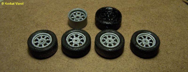
|
|
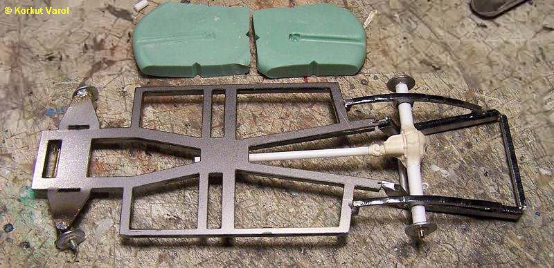
24
January 2011:
I
cut a universal joint from my parts box, made a mold to make the joint
before the differential. Then I cast a part from marble adhesive at the
end of a styrene rod, then glued the part in place.
|
|
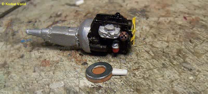
I
began detailing the engine. I made the fan from brass sheet. I made the
distributor from styrene rod and made the cable holes with a heated
needle. For the air filter, I used a metal washer and glued pieces of
styrene below.
|
|
After installing the spark plugs and cables, I glued the other components to form the rolling chassis. 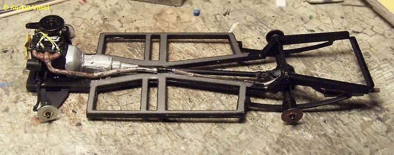
|
|
|
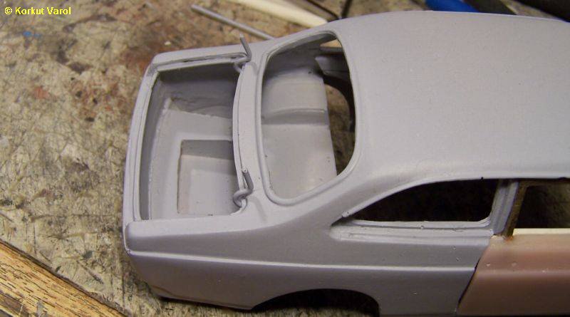
I bent a roll-bar from 2 mm solder wire and checked the fitting. 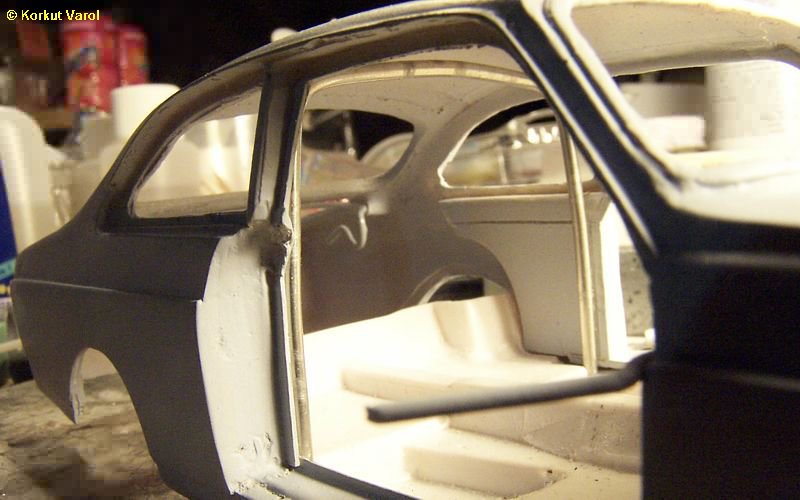 |
|
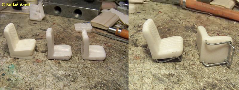
Since the doors were opening,
the seats had to be realistic. So I cut the bottom of two seats to
proper thickness. I
prepared the seat legs from steel wire, inserted them in the holes I
drilled at the seat bottoms, then glued them in place.
|
|
I
shaved the cast window crank arm from the door insides. I drilled the
center and made a crank arm from a headed pin to be placed in place
later.
|
|
|
I made support rods for the boot and hood from 0.8 mm wire. 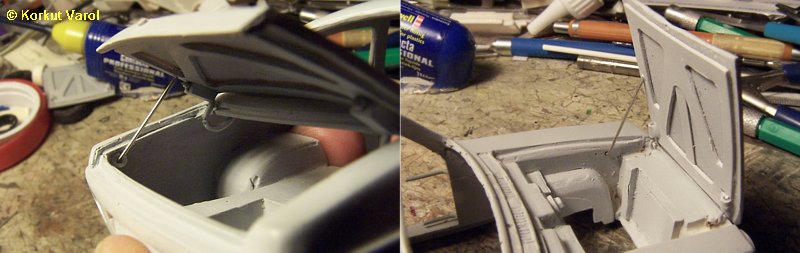
|
|
I made a template for the roof lining, cut from masking tape and applied it under the roof. 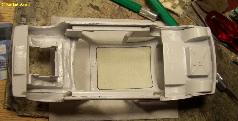
|
|
17
February 2011:
I
made U-bolts from 0.8 mm wire to hold the seats in place, plus act as
hinges. I drilled the floor panel at suitable places, installed the
seats by glueing the U-bolts with CA glue from below. The seats can be
folded just as in the original car. I also painted the roll-bar and
fixed it into place with CA glue.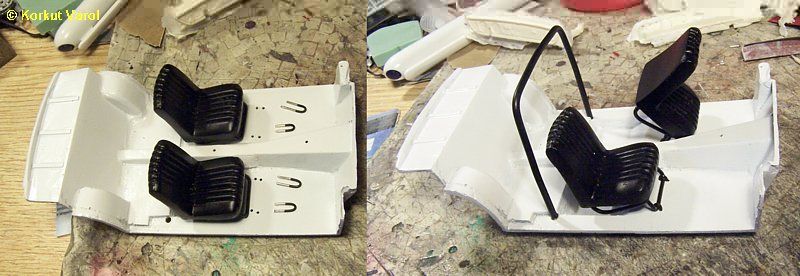
|
|
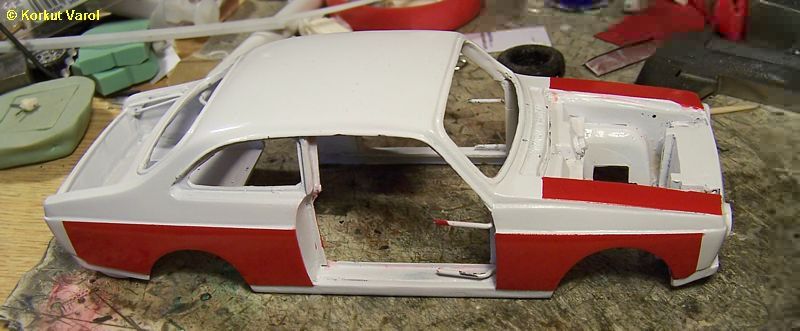
After some painstaking masking,
I painted the body. Some minor overflows will be retouched later.
|
 ..... .....  |