| Building Period: 30 March 1999 - 30 June 1999 |
CONSTRUCTION
STORY OF
SCRATCHBUILT
STREET ROD
|
 |
THE START AND THE CHASSIS
| Building Period: 30 March 1999 - 30 June 1999 |
CONSTRUCTION
STORY OF
SCRATCHBUILT
STREET ROD
|
|
| The story began with my selection of the model to build for the contest in C.A.R.S. I had a '34 Ford 5-window coupe still in its box, so I decided to build one out of that. But then, it occured to me that it should have something distinct - the model would have a working suspension and poseable steering. However, the plastic would never endure the forces generated with a working suspension system, so I decided that the chassis and suspension elements were to be scratchbuilt from metals. Also, once my hand had touched the metal, I could go on building the bodywork from metal and my model would remain intact for original construction. The bodywork, I decided to make it a roadster for better vision of the inside.The most critical point was to make the ball-joints on the front suspension, so I started to manufacture that part first. |
| The wishbone is from opened-up cotter pin. I had that material readily available, so I used it. It might have been a rectangular-sectioned (1 x 1.5mm) copper bar as well. But the semi-elliptical cross section of the cotter pin looked fine, too. The mid part of the rod was ground with the cutting tip of Dremel moto-tool so that a local U-shaped channel was made. This channel would be the housing of the ball joint, when wound around the ball of the kingpin. | 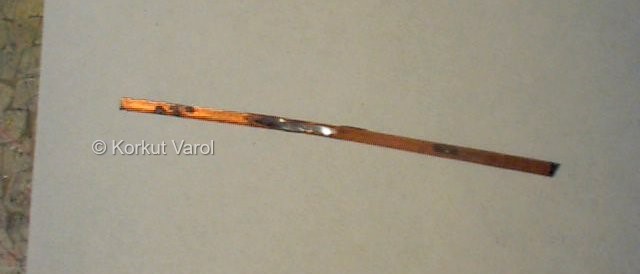 |
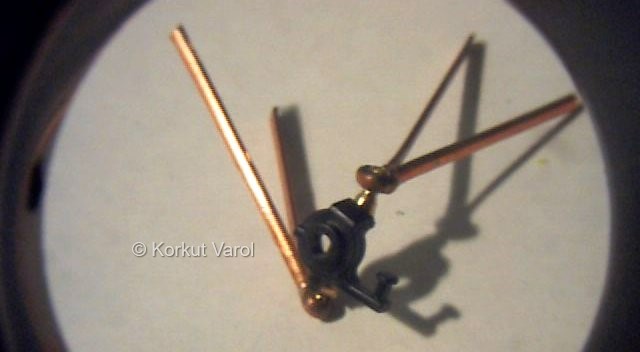
| This is the kingpin. It is made by turning a brass rod with 2.5 mm diameter. The hole in the center is drilled at the proposed kingpin inclination angle, and serves as a guide when the wheel-carrying hub+brake unit is glued on it. The pic at the right shows how the cotter pin envelopes the balls of the kingpin. The rod is wound around the ball and tightened with pincers. This was the time when I saw that this was working OK and decided to continue. | 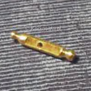 ... ...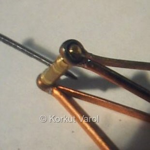 |
| As for the wheels, I had some unused parts (all except for the body) remaining from the "Nascar Beetle", and the wheels looked very elegant so I decided to use them. The VW front hub was glued to the kingpin with 5-minute epoxy. |
 |
| Now that the front suspension barrier was broken, it was time to start the chassis. The side frame member templates were drawn from the plastic model in hand, but 2 mm wider (50 mm in real) than the original to be stronger and carried on to 0.3 mm thick galvanized steel sheet. It was then cut with scissors. For the ones who might tempt to do that, buy your own scissors so that you can be safe from mom's or wife's bullets!!!! | 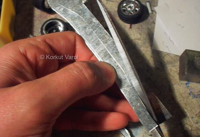 |
| The U-channel section was made by using pliers along the frame and in the end, a warped frame section is obtained. This is to be straightened with very light hammering and by hands. | 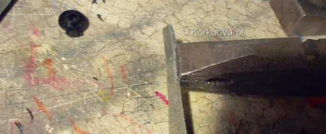 |
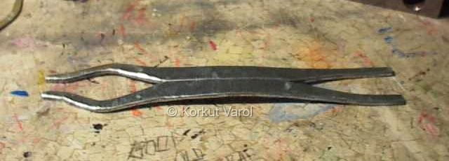
| The final profile is given to the side members by comparison with the original plastic chassis. Here the two members are side by side. |
 |
 |