| Building Period: 30 March 1999 - 30 June 1999 |
CONSTRUCTION
STORY OF
SCRATCHBUILT
STREET ROD
|
 |
.THE CHASSIS AND FRONT SUSPENSION
| Building Period: 30 March 1999 - 30 June 1999 |
CONSTRUCTION
STORY OF
SCRATCHBUILT
STREET ROD
|
|
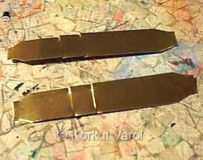
| Now the central cross-members have to be constructed. The original chassis seemed to be weak in construction to take up the stresses of a powerful machine, so the cross-members were built without being faithful to the original. The material used is 0.2 mm thick brass sheet. The developments are traced and cut out. Lightening holes were drilled before bending. Pliers were used for bending. |
 . . |
|
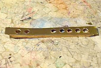
The two sides of the central cross-member are now united with a central section. This central section seen was later cancelled because the transmission had to be there, or else the engine would be too much in the front. |
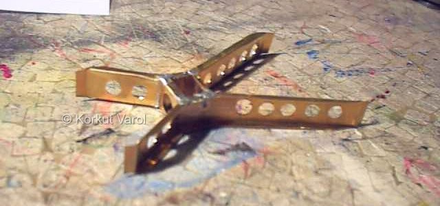 |
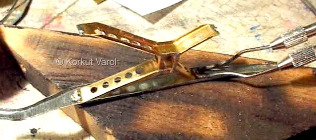
| The side frame and central cross-member are joined with solder. To do this, first the mating locations on the surfaces of the members are covered with solder, then brought together and heat applied with the combined pressure of soldering iron from above. The soldering iron has to be at least 100 Watts to give in heat faster than it dissipates through the metal. The pre-solders between the items melt and firmly hold the pieces together. Be sure to have a low-conductive material (wood is OK) below the workpiece, to keep the heat within the workpiece. |
 |
| The front transverse member is still from 0.3 mm galvanized steel to be strong. The first pic is primary bending after development cutout. The second one is the final shape given with round pliers. |
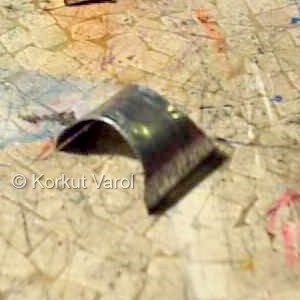 .. ..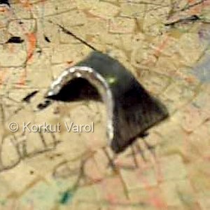 |
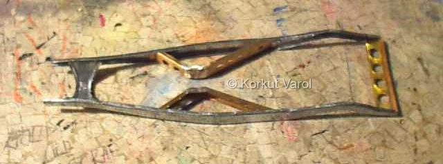
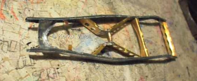
| Now the chassis is semi-complete with the addition of the rear transverse member, having lightening holes on it. The front member was soldered with fill-in technique because the items did not have flat mating surfaces. Note the center part is removed by now. |
 |
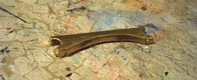
| This is the last transverse member to be located at the very back of the central cross-member, also where the front brackets of the leaf springs be located. The bottom part is curved to provide space for the driveshaft motion. |
 |
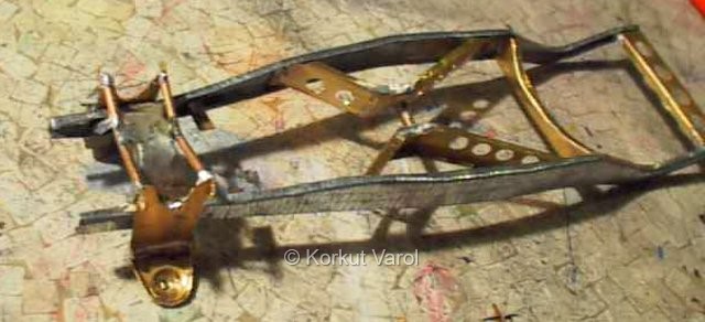
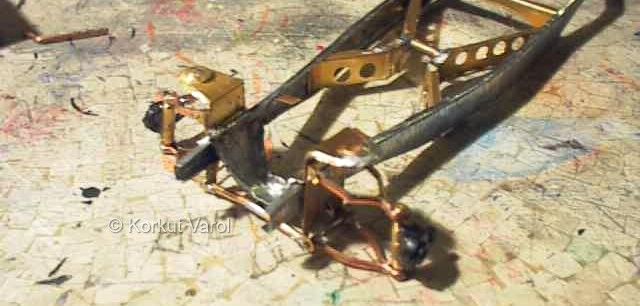
| The chassis is shown with the above mentioned member put in place. Also, two engine mounting brackets are soldered in place. The center element is replaced by a tubular member. |
 |
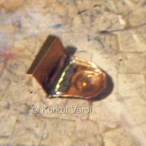
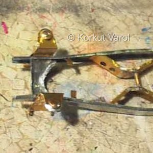
| On the left is the upper bracket that will carry the helical spring and the tip of the shock absorber.For the circular pressed part, a wooden male and female die parts were made and the pressing was obtained by light hammering on the male. The rest was bending with appropriate tools. The inside of the bend was strengthened with filling solder. On the right, you see them mounted on the chassis. Below these units are the parts to hold the wishbones but I was so concentrated on the work that I forgot to take their pics. |
 .. .. |
| This is the bottom view of the front end. Two brass rods were soldered between the lower wishbone bracket edges, also taking strength from the center of the front transverse member. |
 |
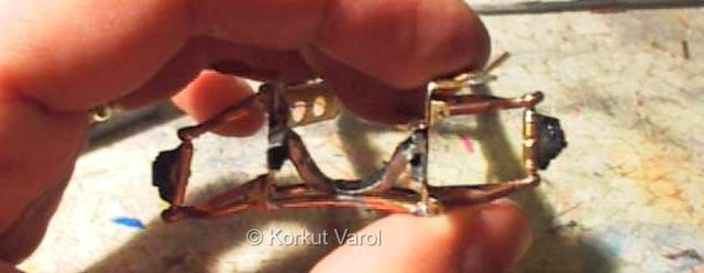
| This is the front ass'y without the springs and shocks. The wishbones were bent to a special profile to make room for the spring. Pins were soldered at the ends of the wishbones, the brackets on the chassis were opened a bit wide to fit the wishbones in their holes, then closed to original position to hold the ass'y without letting it loose. |
 |
| Testing the linkage motion before spring and shock absorber assembly. |
 |
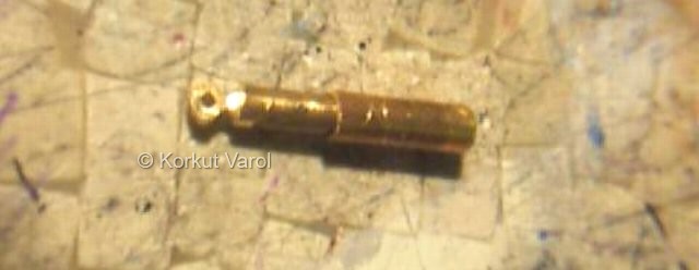
| The front shock absorbers are made from brass rod machined at the end to form the lower eye, and the upper part from brass tubing. On the top, the head part of a nail is cut to 2mm. length and soldered to the tubing to form the upper connection. |
 |
| On the right is the assembled view of the front suspension. The white PVC on top of the shock absorber is a temporary "nut" to keep the upper part of the absorber in place. |
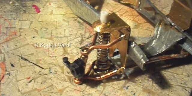 |
| The testing of the assembled front suspension. | 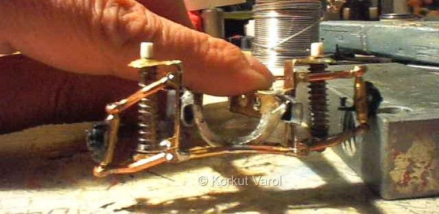 |
 |
 |