| Building Period: 30 March 1999 - 30 June 1999 |
CONSTRUCTION
STORY OF
SCRATCHBUILT
STREET ROD
|
 |
REAR SUSPENSION
| Building Period: 30 March 1999 - 30 June 1999 |
CONSTRUCTION
STORY OF
SCRATCHBUILT
STREET ROD
|
|
| The rear suspension is assigned to be a leaf spring type. The reason was simply to make the model of a different kind of suspension. The leaves are cut from 0.2 mm brass sheet and given an approximate curvature by hand. | 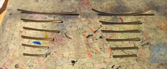 |
| The leaves were pre-soldered (both sides) at their middle and held together firmly with a clamp. The center part was heated with soldering iron to melt and join the leaves. However, the power of the soldering iron proved to be small for the job. There was a lot of metal around to absorb heat faster than the iron could supply. So a small propane torch was used to melt the metal and hold the leaves together. | 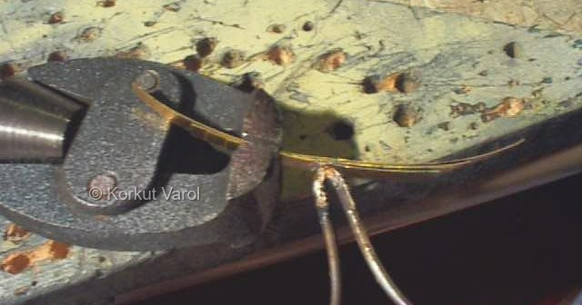 |
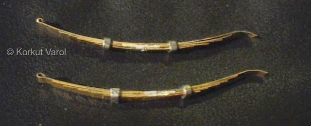
| Now the leaf spring pair was ready for further treatment. | 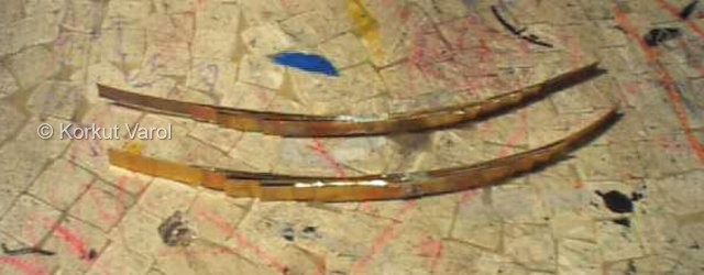 |
| The rear leaf spring brackets are made from 1 mm thick brass sheet at the outside, and 0.2mm thick brass sheet at the inside. The pin holes are being drilled on the outer element in the picture at right. | 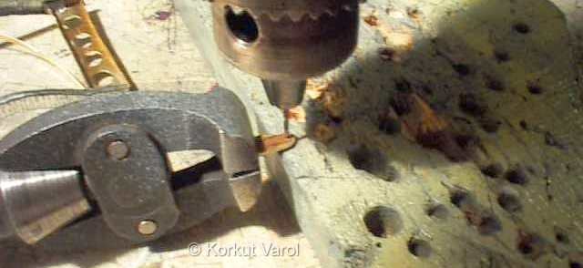 |
| The inner and outer elements of the bracket are being soldered. The unit resembles the letter "h" and the side and bottom surfaces of the chassis will mate with that "h" profile. | 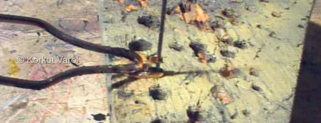 |
| Now the bolting holes are drilled with 1mm. drill and pins located in the holes to resemble the bolts. They are fastened by CA glue and after drying, the protruding stems of the pins are cut off flush with the surface. | 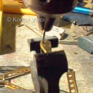 ... ...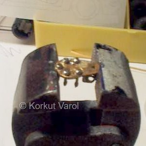 |
| The spring brackets are fastened to the chassis with 5-minute epoxy. Trying to solder them would melt away the solder that grouped the "h" shape of the brackets. The rearmost brackets were too small to handle for drilling, so the imitations for bolt heads were made by applying tiny droplets of CA glue. | 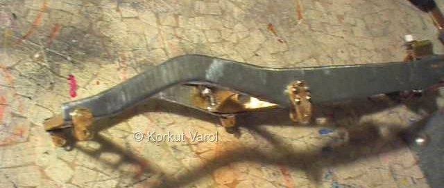 |
| The front eyes of the leaf springs are made by wrapping the end of the first leaf over a pin and defining the roundness of the eye by squeezing with pincers. The excess part left after forming the eye is cut off with the cutter tip of a Dremel moto-tool. | 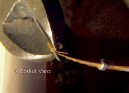 .. ..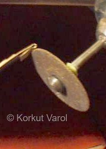 |
| The other end
of the spring is of sliding type, and its profile is formed by hand.
|
 |
| A test mounting of the springs to see if things are going OK. | 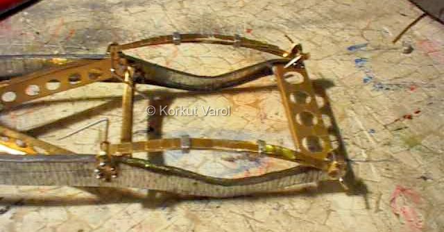 |
| The height of the spacer block between the spring and the axle is calculated and suitable blocks from eraser are cut with X-acto knife. The rear axle is turned from a steel rod ready in hand and channels were machined at both ends to house two snap rings that will aid in defining a perpendicular plane for the mounting of the rear hub parts. The blocks are secured on the axle by CA glue. | 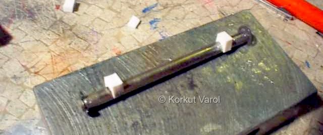 |
| The differential is home-cast resin by using the differential housing parts of a '67 Mustang still in its box. The front and rear halves are brought together on the axle and the small gap left between them will be filled with putty. | 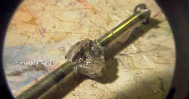 |
| Now the axle is glued on to the springs with 5-minute epoxy. Care was taken to maintain correct wheelbase and intermediate measures were made to make sure that the axle did not slip while curing. | 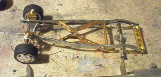 |
| The U-bolts were made from pins and the tightening plates from 1 mm lead sheet. Holes were drilled on the plates so that the U-pins (Sorry....U-bolts) would go through them. | 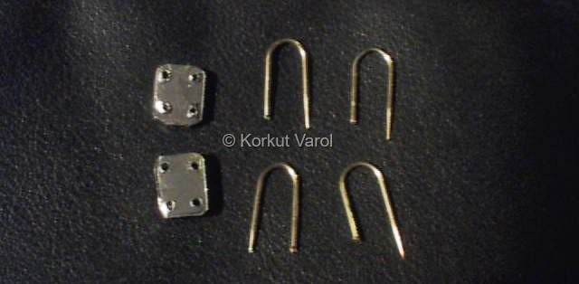 |
| The assembly is held together by 5-minute epoxy glue. | 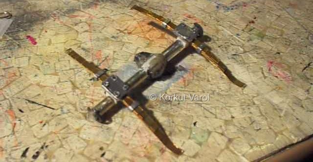 |
| A close-up of the U-bolt region. | 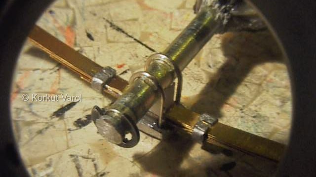 |
 |
|