| The Lynx ProjectLincoln-Mercury’s Lost Dream Car |  |
 |
BUILDING THE SCISSORS JACK
Page: 1 of 5| The Lynx ProjectLincoln-Mercury’s Lost Dream Car | |
|
BUILDING THE SCISSORS JACK
Page: 1 of 506 November 2004:
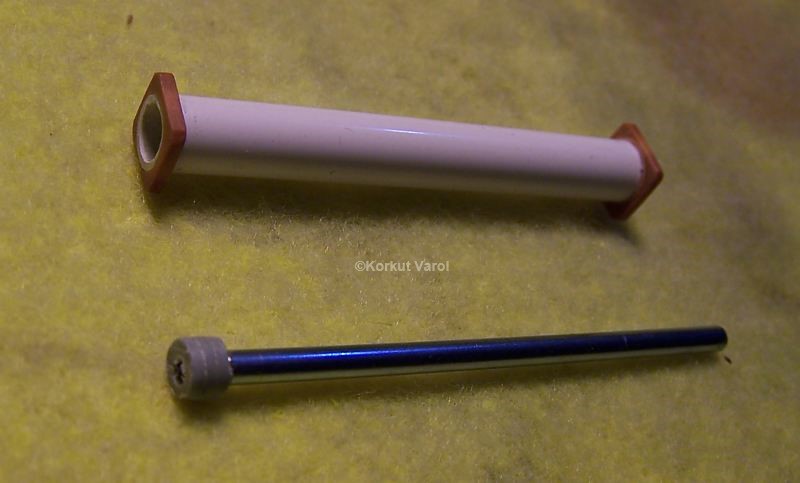
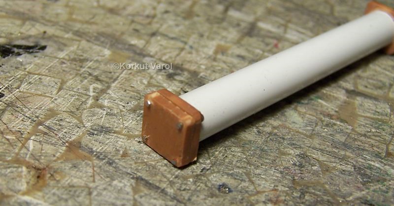
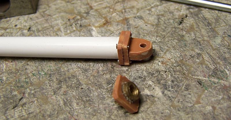
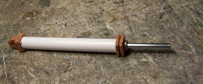
I began by manufacturing the hydraulic cylinder and piston. The cylinder body is from styrene tubing and sheet; the piston rod is from steel, joined by screw thread at one end with plastic piston.
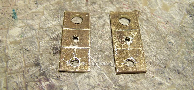
01 May 2005:
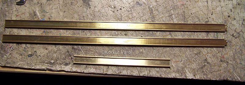
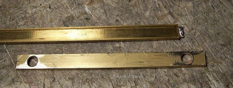
The part with holes is the rearmost member of the chassis, the holes being for the rear lamps.
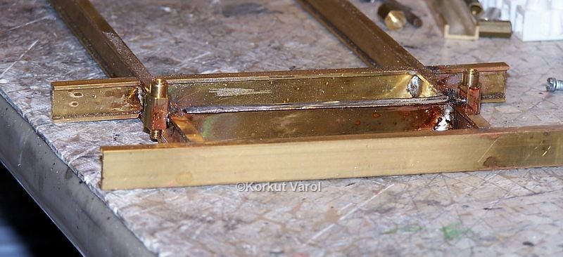
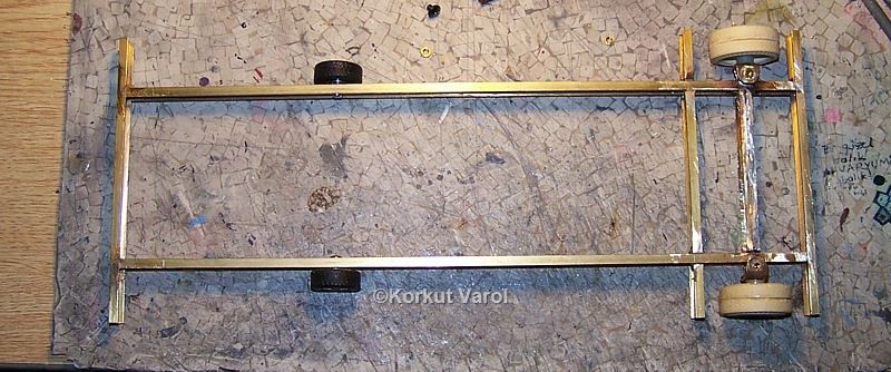
04 May 2005:
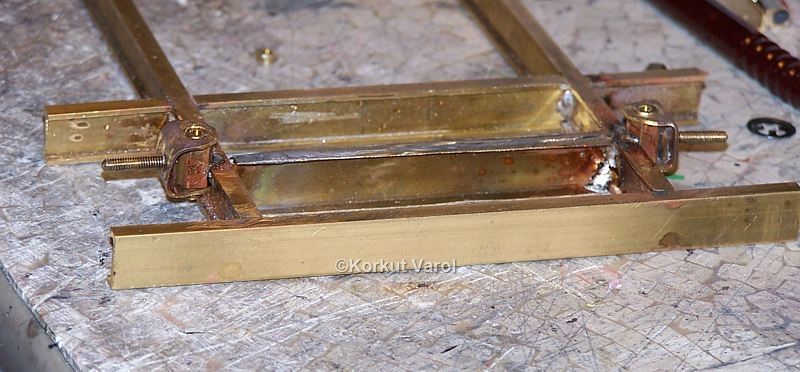
I soldered the chassis longitudinal and cross members by fixing within a frame vise.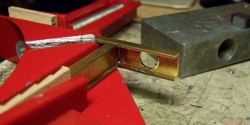
06 May 2005:
The basic construction of the chassis is done.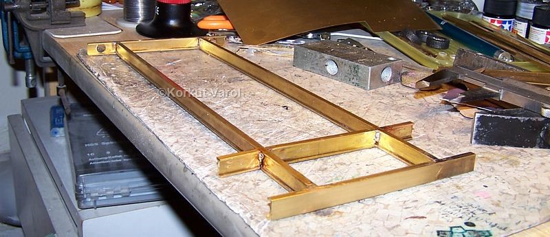
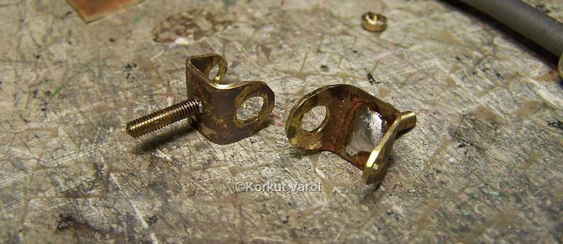
07 May 2005:
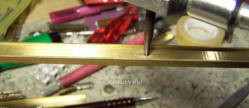
Returning to the hydraulic cylinder, I cut the end plate from styrene sheet and glued it at one end of the cylinder. I drilled the holes for passing pins to imitate bolts. 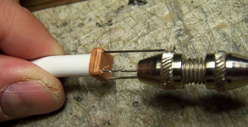
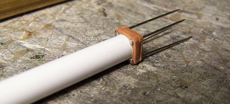
The ends of the pins are cut.
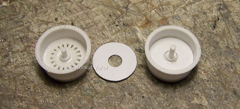
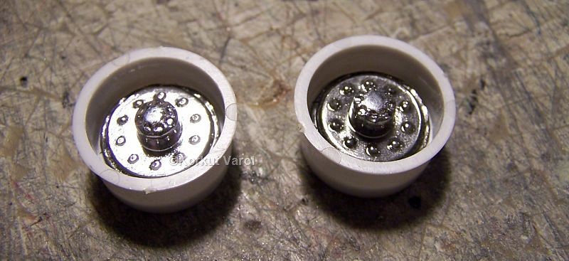
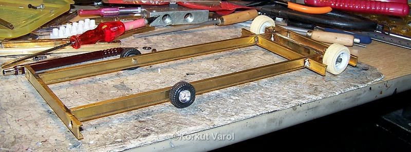
I
used wheels from Lancia Delta Rally kit as the basis for manufacturing
the traction wheels. I also used resin-cast tire halves.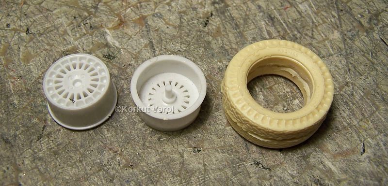
| GO TO: | |||
| Lynx - index |
|  | |
