| The Lynx ProjectLincoln-Mercury’s Lost Dream Car |  |
 |
BUILDING THE SCISSORS JACK
Page: 2 of 5
| The Lynx ProjectLincoln-Mercury’s Lost Dream Car | |
|
BUILDING THE SCISSORS JACK
Page: 2 of 5
03 December 2015:
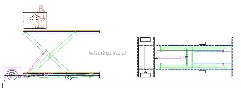
After a long hiatus and having finished the plane, I started designing the scissors jack. I figured out designing the lifting mechanism, which took about two months.
04 December 2015:
05 December 2015:
06 December 2015:
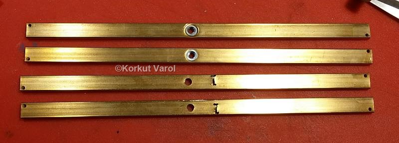
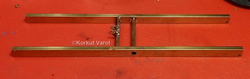
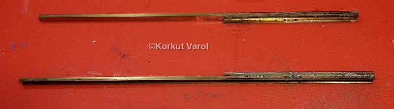
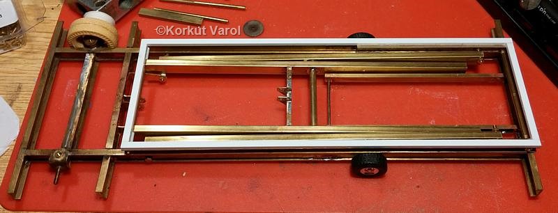
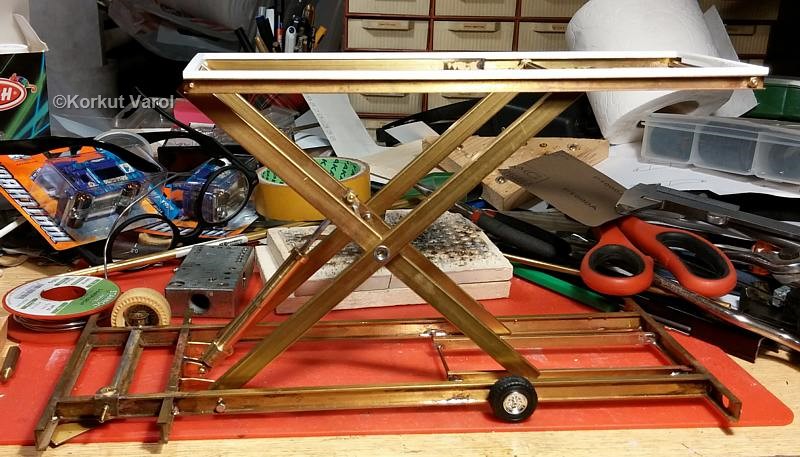
I prepared, cut and soldered the fulcrum brackets and lower rails for the scissor beams.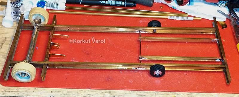
12 December 2015:
For the rollers at the beam ends, I made use of M2 screws. To prevent scratcing of the paint while in operation, I thought of covering the screw heads with black gun glue. I dipped the screw head into hot glue in a die and trimmed the excess after cooling.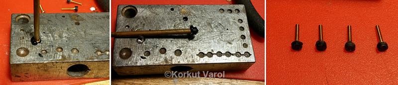
14 December 2015:
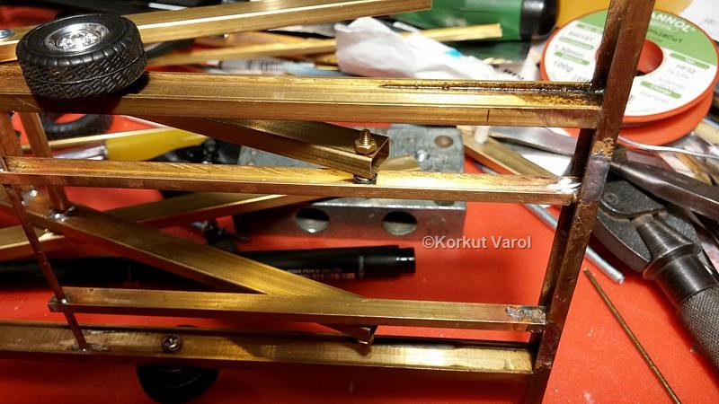
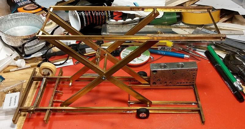
I cut the main platform beams from brass C-sections and soldered the rails for the upper rollers of the scissors.
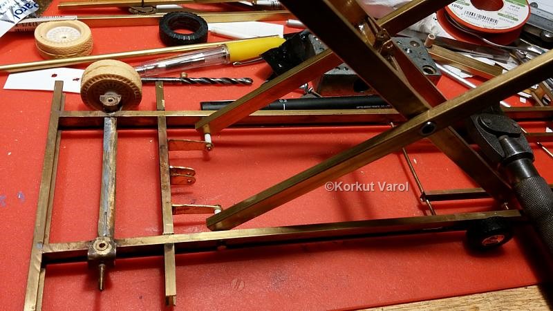
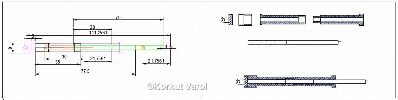
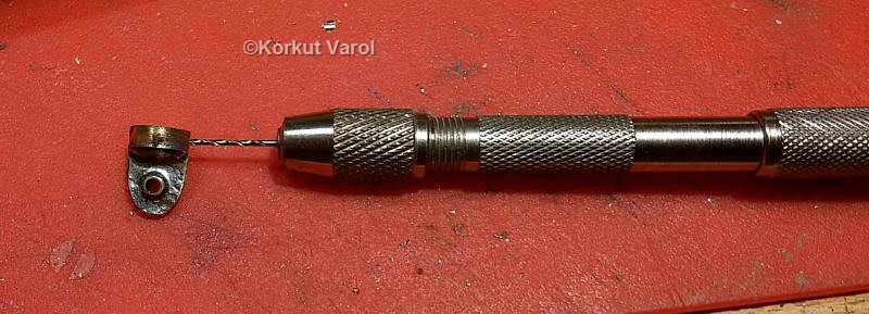
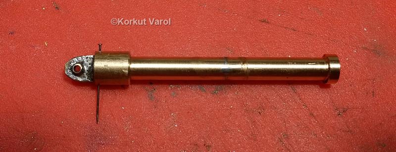
Coming back to the hydraulic piston+cylinder; I had been thinking about a method to provide adjustable height for the platform. Finally, I ended up with a good solution that made the previosly manufactured one obsolete. I designed a multi-pieced unit, where the body of the cylinder is free to turn inside the base bracket. The cylinder has a M3 threaded section in the middle, which houses the M3 threaded end of the piston rod. Since both pin-joint ends are not free to turn abut the cylinder axis, rotating the cylinder body will end up in linear displacement of the piston rod. The cylinder body is broken into two mating parts, to make threading possible.
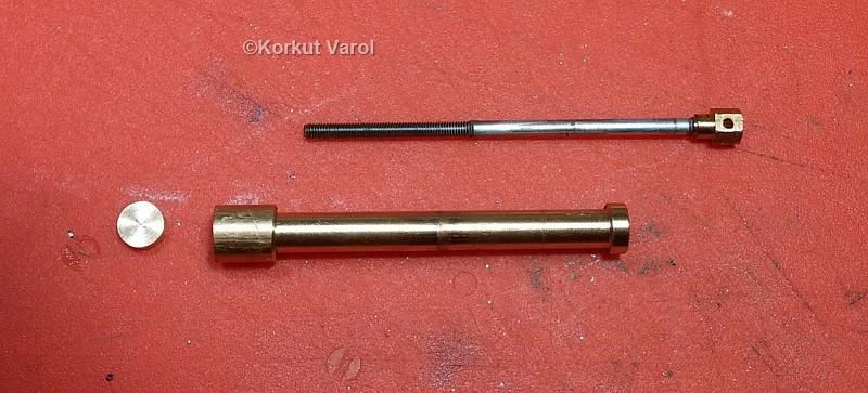
I joined the cylinder parts with solder, and prepared the end pin-joint head for the rod.
| GO TO: | |||
| Lynx - index |  |
|  |
