| The
first thing done was to draw a side view of the wagon. I drew this from
the collection of images I downloaded. |

|
| The
parting line of the roof was drawn.. |
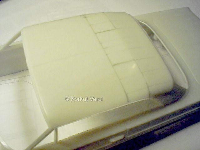
|
| ...and
cut off as well as the boot. |

|
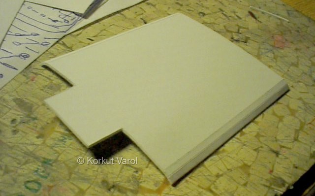
| The
roof extension was traced on a styrene sheet and cut off, then given
the
first approximate shape. |
|
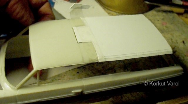
| The
extension was glued to the front part. |
|
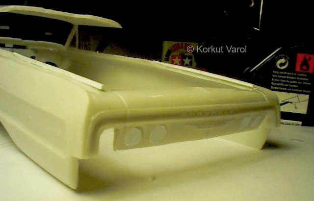
| I
filled 4 of the rear lamp holes with styrene, then opened the outermost
one with a file to accept the rectangular taillight. |
|
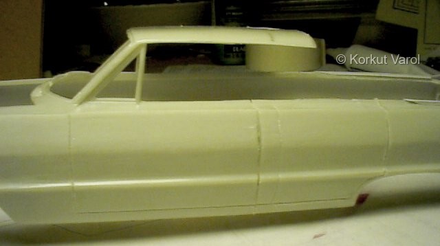
| I
then re-scribed the door parting lines as per 4-door body, |
|
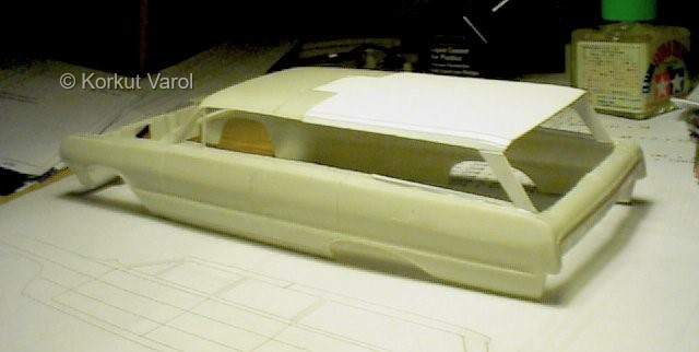
| ...and
glued the roof extension with the D-posts. The roof will be aligned
with
the insertion of the B and C-posts.
The project
was given a break for almost 3 years, till I could start it again in
December
2003...
|
|
| Restart
on Dec.1st,2003:
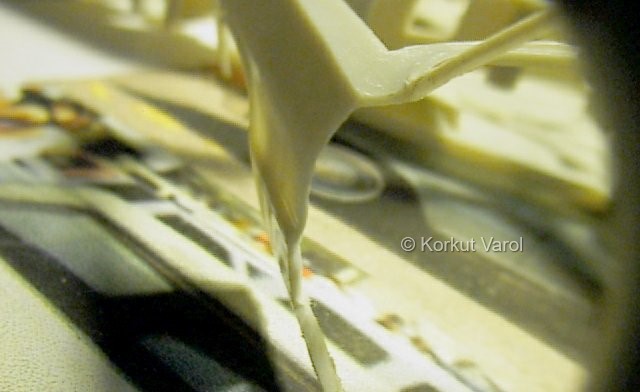
I cut
away three doors, leaving the rear left in place. The reason was that
the
Dolmus cars always had them closed too, for uncontrolled operation that
might lead to danger for the oncoming traffic. The inner handles and
window
cranks were also removed at the rear left door.
I
thinned the generously molded plastic at all the opening edges.
|
|
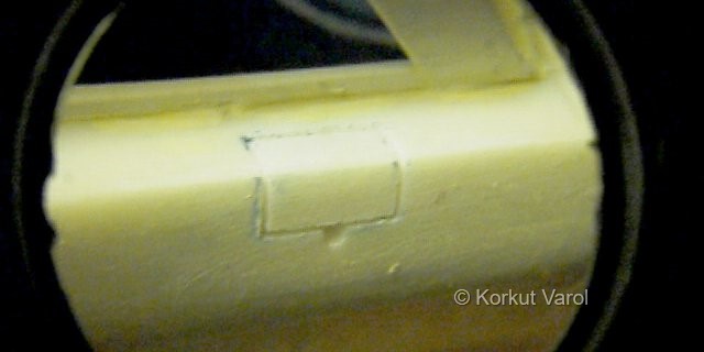
| I
scribed in the tank cap lid for the wagon. |
|
| Dec.
9th, 2003:
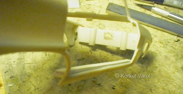
I cut
styrene strips for the upper sides of the rocker panels and glued them
as two layers. The lower layer is for the fixing to the inside of the
rocker
panel, and the upper one standing for the small step that the door
bottom
will rest against.
|
|
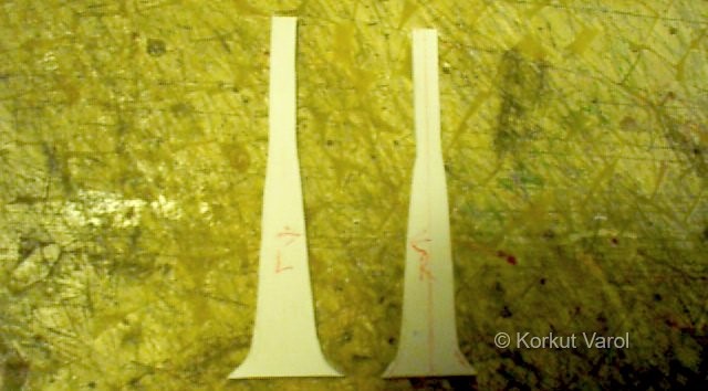
| Now
for the B-posts. After hunting on the net for several days, I could get
enough details to manufacture the real-looking inner parts. This is
also
my first attempt to open a rear door, hinged at the B-post, with the
opening
axis like the original; so that when open, it will not prevent the
front
door from opening. I first cut the backing sheets. |
|
| Dec.
14th, 2003:
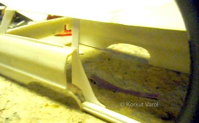
The
C-post backing sheet was also cut and glued in place. Some layers of
styrene
will follow to fill the gap to the fender.
|
|
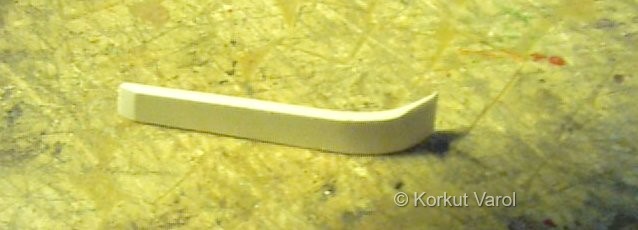
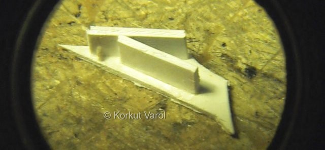
| This
is the slanted part starting below the door lock and going down to the
top of the rocker panels. Note how the edges are sanded for smooth
transition. |
|
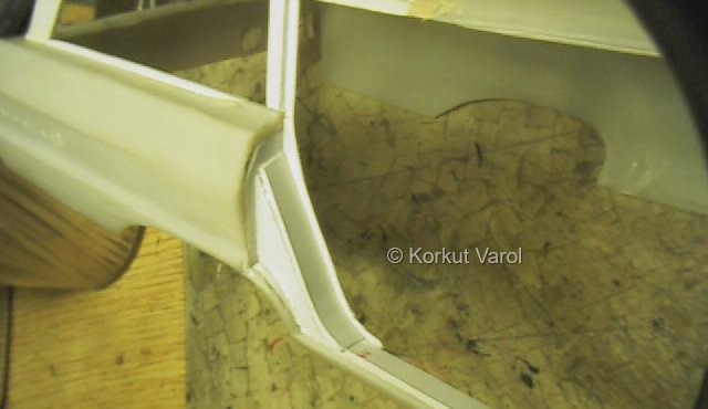
| This
is the side covering panel for the part described above. The spacers
glued
will serve for proper positioning and fixing on the backing plate of
the
C-post. |
|
| Now
you see all the above parts glued in place. |
|
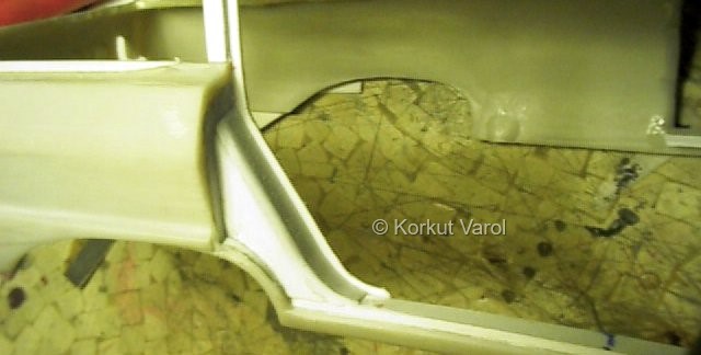
| ...then
sanded smooth. Later, putty will take care of the details. |
|
| Dec.
16th, 2003:
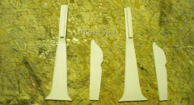
Coming
back to B-posts, I cut out more sheets...
|
|
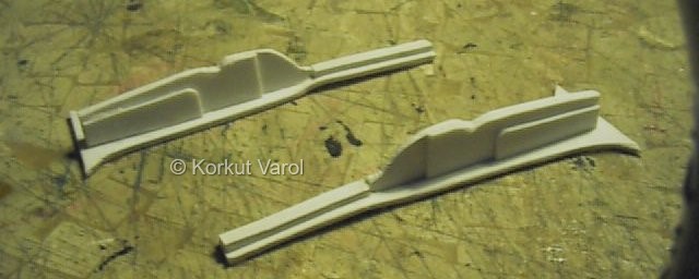
| ...and
assembled them. But I did not glue them in at this stage, because the
rear
door hinging had to be manufactured and tested before glueing the
B-post
in. |
|
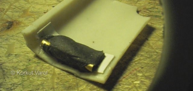
| A
brass pipe was cut and fixed in place with "steel putty". This is the
integral
cast two-part putty that you knead to uniform color and sets quickly.
Very
handy for adjusting the final position. I adjusted the turning axis so
that it passes right close to the lower front corner of the door panel. |
|
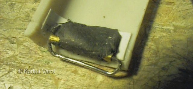
I
bent a steel wire from paper clip in such a manner that, of the open
ends,
the upper one is a bit longer than the lower one. This helps in
mounting
and dismounting the hinge. To mount, the pipe is first fed over the
upper
end of the wire, which clears the lower end. Then the door is left
freely
down on the lower end of the wire and it stays on, because the longer
upper
end is still within the pipe and holding it.
Now,
this wire will be tested against the B-post, and on the body. |
|
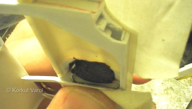
| It
took 4 wire manufacturings to get to the correct shape.while holding
everything
in place temporarily, I applied CA glue on the wire and kept still
until
it cured. |
|
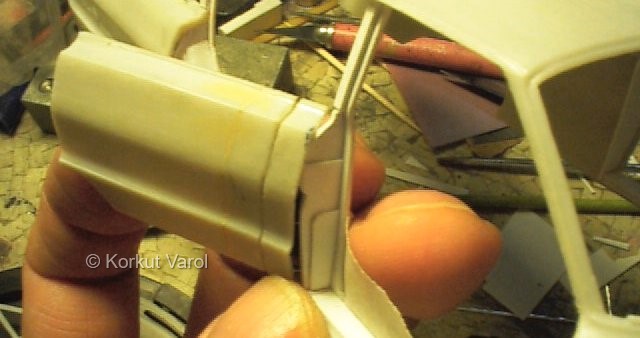
| The
first opening attempt showed that there was some limitation for opening
enough. The Clashing part on the B-post was sanded down until a
satisfactory
opening angle was reached. |
|
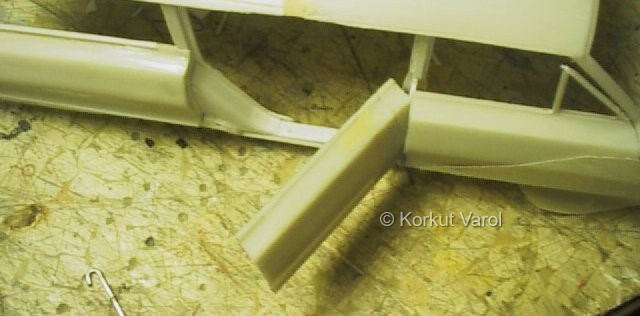
| VOILA!!!
Now the front door can be opened after the rear door! |
|
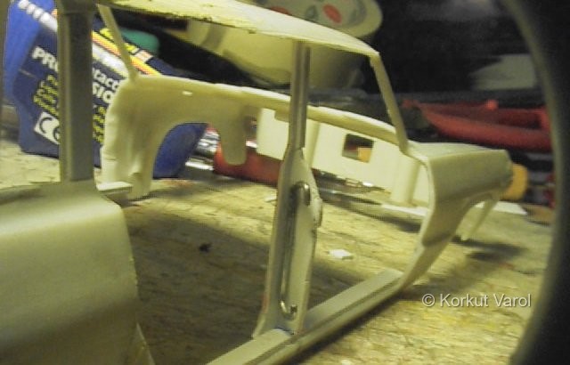
| This
is the looks after the door is removed. |
|

|

|


