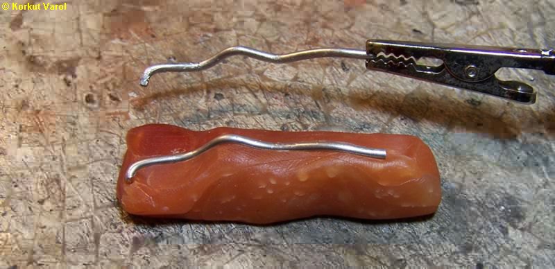
13 December
2009:
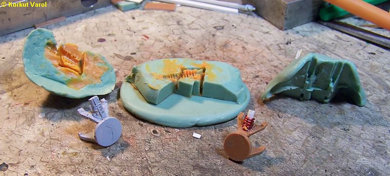
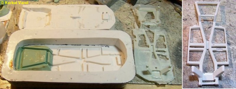
I made the
front suspension assembly
master (right, brown), then prepared a 3-piece mold for casting. I cast
the first sample (left, gray).
|
14 December
2009:
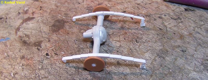
I constructed
the rear axle and suspension.
I used an axle from an AMT kit and built the springs from styrene
strips.
I will make a silicone mold from this master.
|
|
16
December 2009:
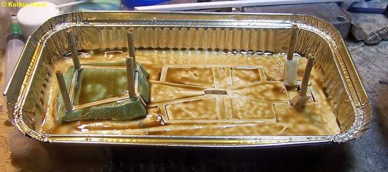
I made the
lower part of the silicone mold
for the chassis and applied liquid grease before pouring the upper part
to prevent sticking. The upright sticks are the runners for venting
during
resin pouring.
|
17 December
2009:
I cast a
sample. The one very near
the mold is the raw casting. At the rightmost, after trimming. There
are
some gaps due to trapped air but that is not important because they
will
be unseen when the floor panel is glued on top.
|
|
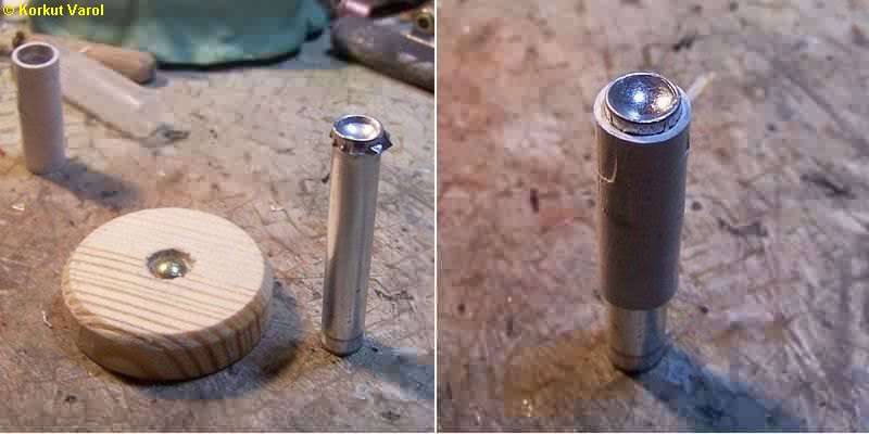
21
December 2009:
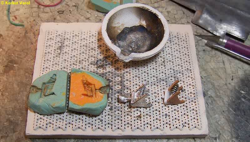
I did not like
the way that the front wishbone
assembly turned out. The casting had problems and the disc came out
oval.
I changed the design and made another, then cast a resin sample;
however,
I did not like this resin too, because it was too weak. So I thought of
casting in metal and made a casting from solder. Now this was
satisfactory.
In order to cast in one piece, the space between the kingpin and the
coil
had to be filled.
|
|
04 January
2010:
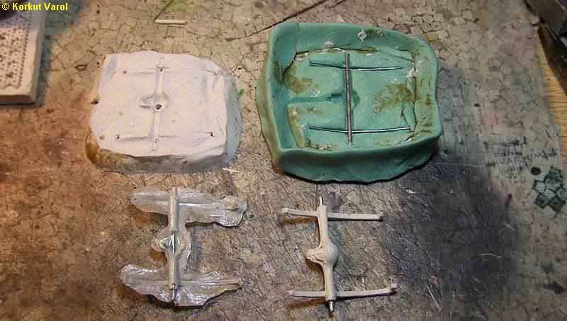
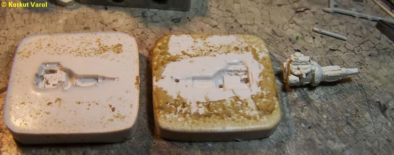
I made the
silicone molds for the rear
axle assembly. Since the cast part would be too brittle, I inserted
wire
reinforcements inside the springs and the axle. My resin casting
attempts
were a catastrophy, the upper part of the differential housing never
filled
up (left). So I cast the part using marble adhesive (right).
|
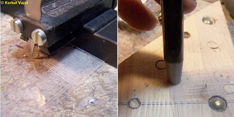
17 January
2010:
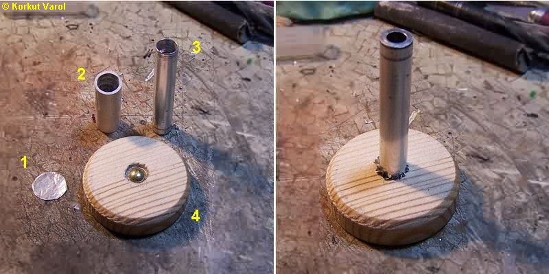
After several
attempts for headlight reflector
and bezel production, I made the production as below:
1- 0.1 mm
aluminum sheet for the part
2- Plastic
pipe piece with internal
dia. 8.5 mm
3- Male die
from 8 mm aluminum tubing
that I made by turning the inside to 7 mm dia. at the front end
4- Female die
from wood. I inserted
a metal thumbtack to form the reflector.
As in
the right photo, I pressed the
workpiece between the dies.
|
|
In
the left photo, the workpiece
is on the male die with corrugated skirt. In the right photo, I passed
the plastic pipe over the workpiece to iron the corrugations.
|
|
I
positioned the plastic pipe close
to the end and trimmed the bezel. In the right photo is the finished
part.
|
|
For
the lens, I made cross scratches
on a piece of acetate sheet. Then I punched out a part.
|
|
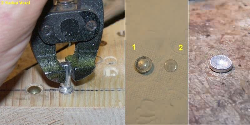
I
shaped the lens between a heated
aluminum male and the female in a piece of wood. In the central photo,
(1) I filled the back of the reflector with superglue to prevent
deformations.
(2) is the finished lens. The rightmost photo is the glued
lens+reflector.
|
|
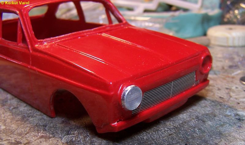
To
make a check, I put the headlamp
on the body. The bezel height should be reduced a bit.
|
|
19 January
2010:
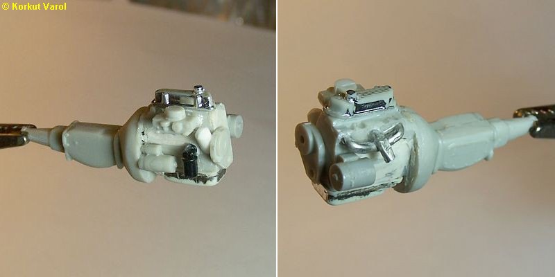
For the engine
and gearbox, I made use
of Opel GT V6 engine. I shaved the V-heads, filled the gaps with putty
and shaped the block and cylinder head. I shaped the valve cover from
Opel
GT's. I used suitable parts from my parts box for the oil filter,
starter
and intake manifold. I made the exhaust manifold from 2 mm solder wire.
I shaped the oil sump from a bigger one. I will take a silicon mold
from
this master now. Since the hood will be closed, this much detail is
enough
for the engine. The gearbox and its tail, though not exactly, are
tolerably
close to scale so I did not attempt for any modifications.
|
20 January
2010:
I made the
mold for the engine and
gearbox, and made a sample casting.
|
| I
glued the engine and rear axle assembly
on the chassis and shaped the exhaust pipe from 2 mm solder wire. Since
inserting the pipe was too tough, I made it two pieces, front and rear.
|
|
20 January
2010:
Since the
shape of the frontal exhaust
pipe was somewhat complicated, I decided to make a bending jig to
manufacture
the pipe from 2 mm dia. solder wire. I made use of FIMO polymer clay. I
embedded the original pipe half way inside, then baked in the oven to
get
it hard. The photo below shows the original pipe (above) and the
bending
jig and a formed part (below).
|
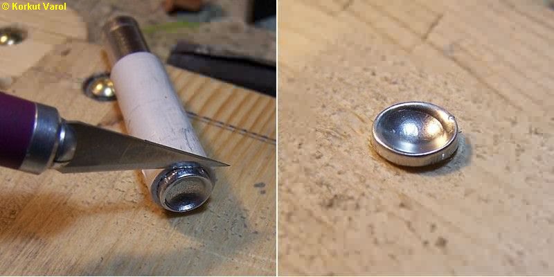
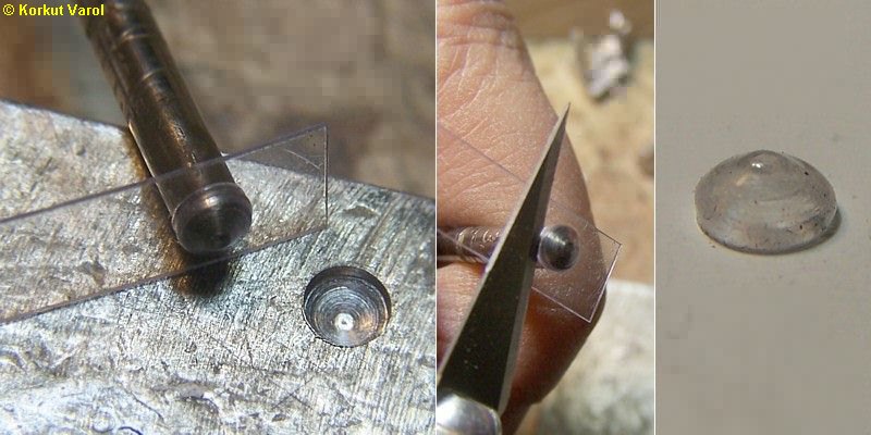
| I
manufactured the signal and stop
lamps as below. First I shaped the backside of a drill bit to the part
and drilled a female in a metal block. I heated the drill bit and
formed
0.2 mm thick acetate sheet between the male and female parts (left).
Then
I trimmed the lamp cover by a cutting knife (center), to end up with
the
part itself (right). I tried pre-painting the acetate with glass paint
and then forming, it works fine too.
|
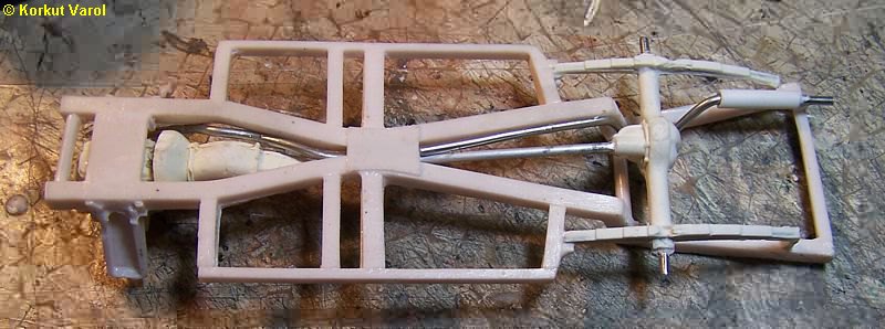
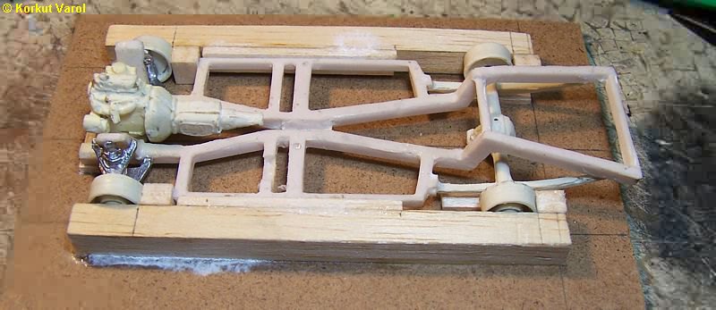
| Due
to the space of freedom between
the parts, mounting the front wishbone assembly brought along a high
risk
of erroneous glueing. So I made a jig for glueing the front and
rear
wheels orthogonally and at at correct places to the chassis. Then, with
the wheels in place (for correct positioning) I glued the front and
rear
axles to the chassis. The wheels can be taken off.
|
| |
 ...... ...... ... ...
|