


| The Lynx ProjectLincoln-Mercury’s Lost Dream Car | |
|
BUILDING THE DC-8 PLANE
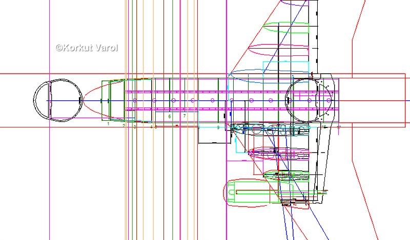
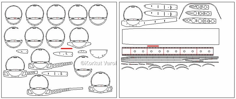
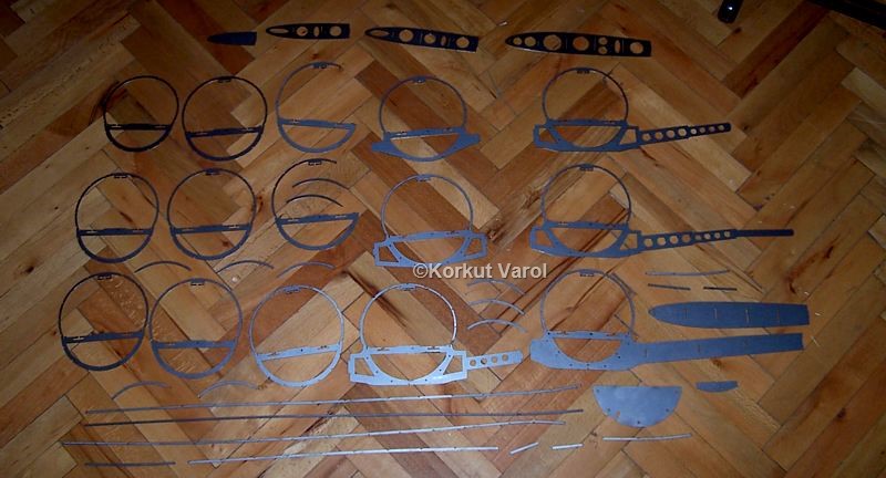
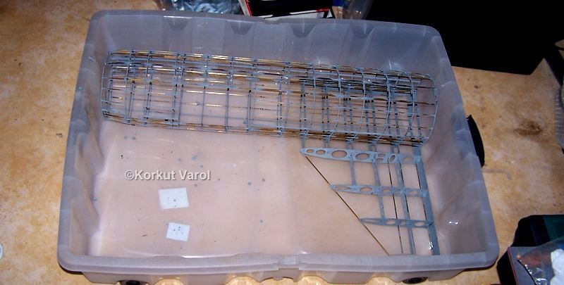
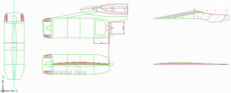
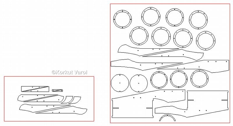
After some months of designing and drawing the structure of the DC-8 plane on Autocad, I finally had the formers and other parts cut from sheet steel with a CNC laser cutter.
24 June 2011:
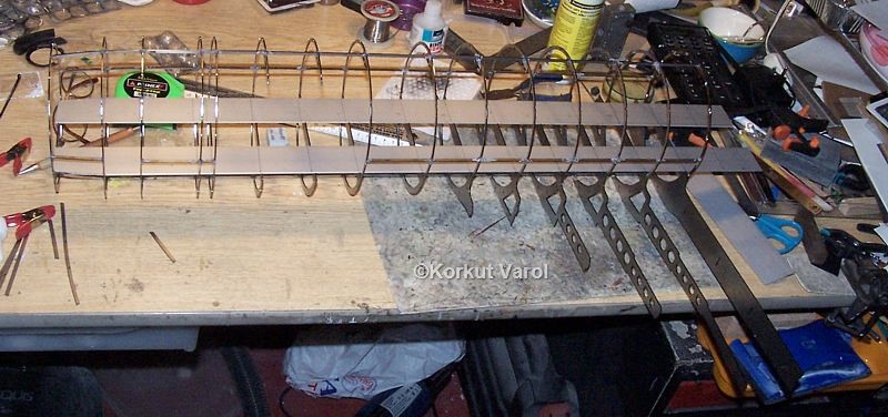
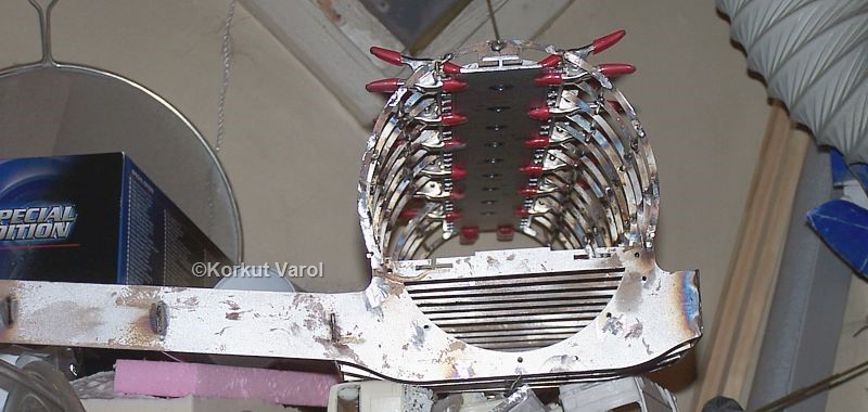
I completed soldering the stringers. In the photo below, the mating of the aluminum profiles with the formers are seen.
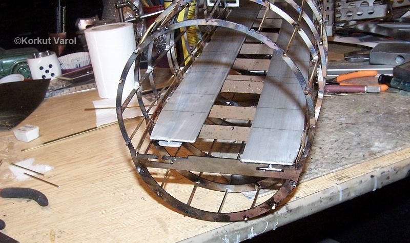
25 June 2011:
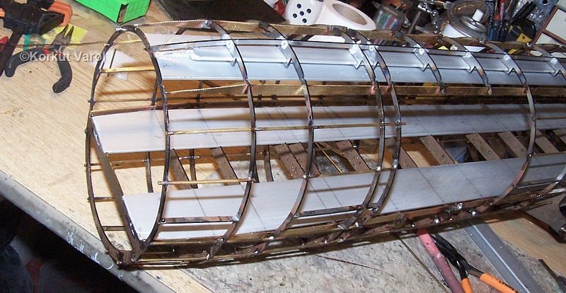
Now was the time for fixing the floor panel to the aluminum profiles. Before fixing, I scraped both the floor panel and the aluminum profiles for better grip of the adhesive.
26 June 2011:
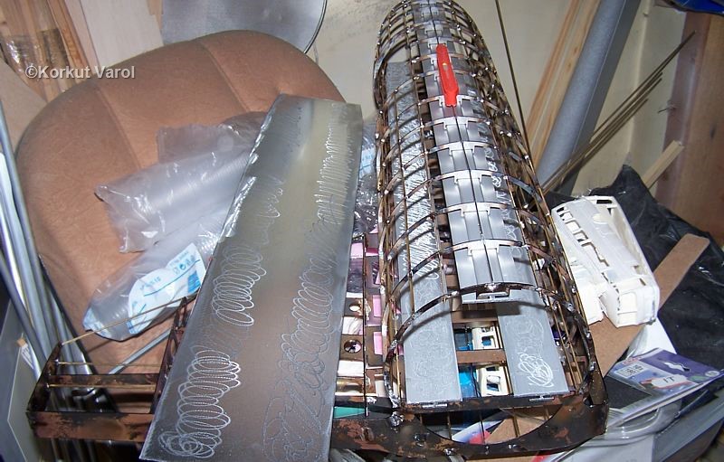
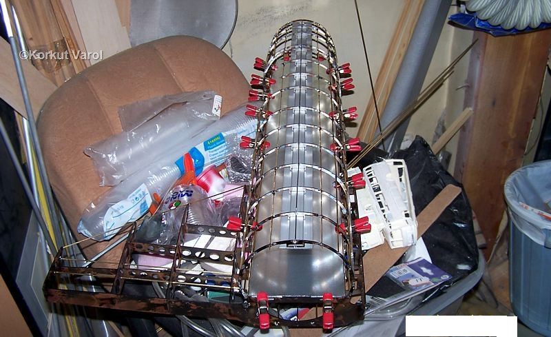
After the floor cured, I did the same with the fuselage ceiling.
The stringers were brass, but since the formers and ribs were steel, to prevent rust forming risk in the future I applied Zinga (cold zinc coating) on the formers and ribs.
17 July 2012:
Spending some long time on how to manufacture the engine, I finished the sectional Autocad drawings that would be the basis for construction of the engine.
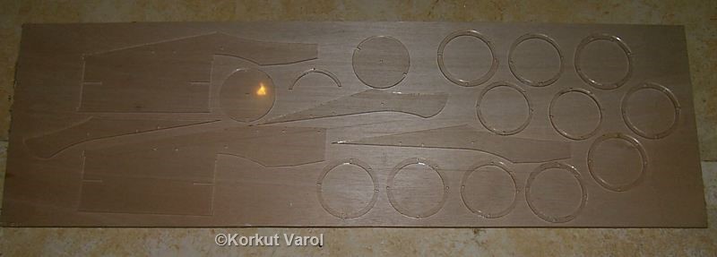
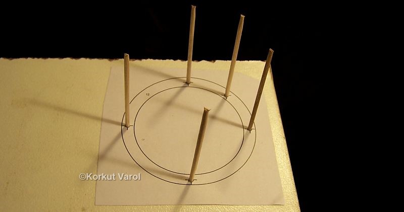
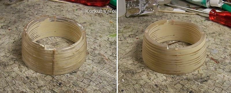
I began with assembling the intake part of the nacelle. In order to assemble them perfectly concentric, I printed a template on sticky paper, stuck it on a piece of wooden plate, drilled the guide holes and inserted the guide toothpicks which would aid exact alignment of the layers.
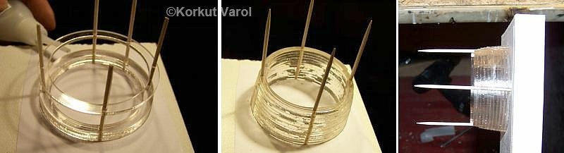
I continued with the assembly of the engine body frame and pylon. I made use of indexing holes for correct positioning of the glued layers.
This is the finished rough "skeleton" of the engine and front intake part.

23 July 2012:
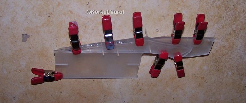
To manufacture the nozzle, I drew the development on the computer, printed on a sheet of sticky paper and used it as a template by sticking on a plastic sheet. Then I cut the development out.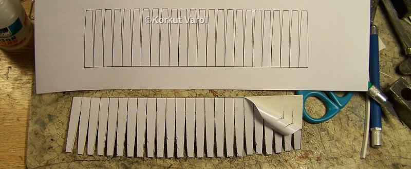
24 July 2012:
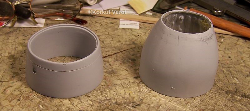
I added the raw plastic material for the bezel of the intake, also joined the nozzle development to a rounded cone. I used CA glue to join the edges of the development. I applied automotive polyester putty on both parts and sanded to proper shape. 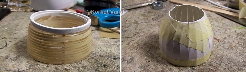
28 July 2012:
I turned the central pod from aluminum rod, and cut the compressor blades from a Sprite can.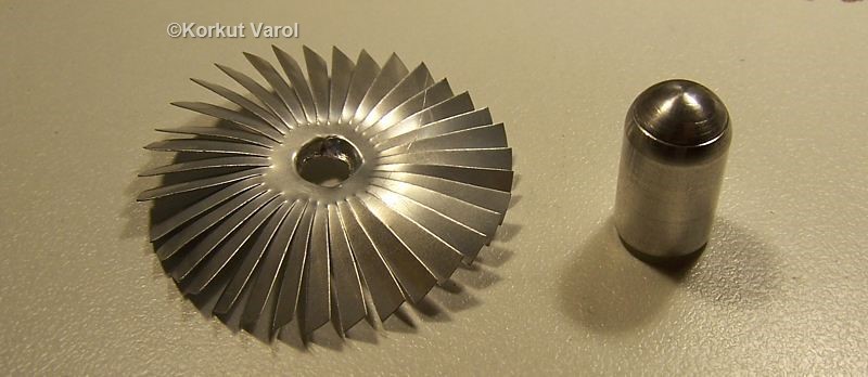
30 July 2012:
For the inlet guide (stator) vanes, I cut strips from a copper sheet, rolled the inner and outer rings, fixed the ends with solder. I cut the vane blades also, and formed a slight twist along each blade.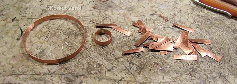
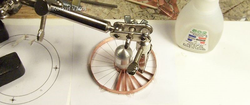
I fixed the pod and the rings on a template and fixed each guide vane blade with CA glue.
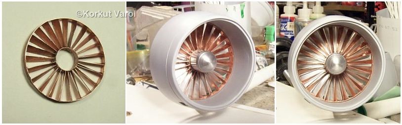
After finishing with the stator guide vane assembly, I made a test-fit .
| GO TO: | |||
| Lynx - index |
|  | |
