|
|
(Selvi Boylum Al Yazmalim) |
 |
 |
|
|
(Selvi Boylum Al Yazmalim) |
|
|
Scale : 1/24
Started:
12 December 2007
Finished: 04
May 2016
Page 2 / 9
|
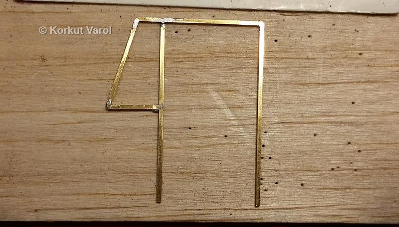
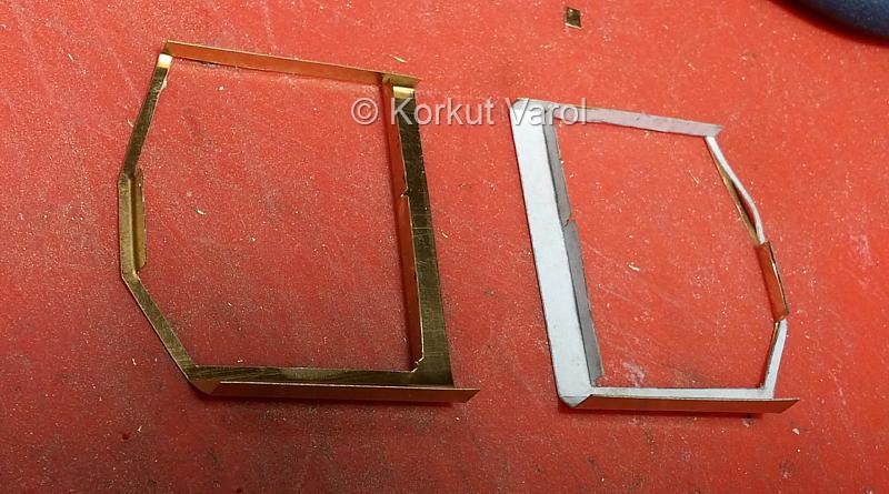
27 February 2016:
I thought of operational windows. I made the frames and slides from 1x1 mm brass U profiles.
|
|
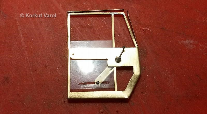
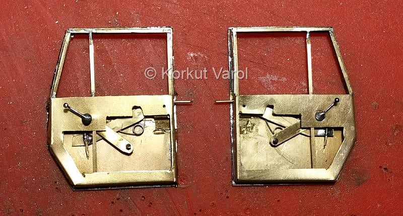
28 February 2016:
I made the
window crank arm by bending a headed pin. Both for positioning parallel
to the panel and to give a real look, I soldered a small disc to the
crank arm where it penetrated the panel. On the back side, I soldered
the lever arm that I made from brass sheet. At the other end of the
lever arm, I soldered the head of a pin and passed it through a slot in
the acetate sheet serving as glass.
|
|
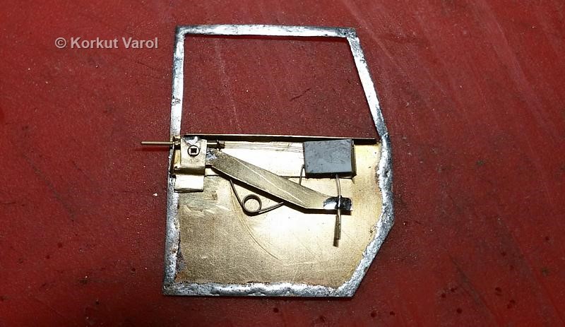
02
March2016:
The lock
mechanism that I had prepared before, got loose at joints and the
exterior handle began to drop down even under its own weight. So I
decided to change the design. After some number of trial and errors, I
ended up with this solution:
I cut the female bearing for the handle from 1.6x1.6x0.9 mm square brass tube. I soldered this to the arm from a brass sheet. I soldered a piece of 0.7x0.5 mm brass tube at the other end of the arm. For the latch itself, I used a brass tube of 0.7x0.5 mm. I made a slider tube from 1x0.8 mm brass tube and passed the latch through the slide tube. I inserted a 0.4 mm dia. fishing line through the latch tube and fixed the fishing line by pressing one end of the latch tube. I passed the other end of the fishing line through the tube on the arm and squeezed another piece of tube to fix the fishing line. The fishing line takes the bend through a closed conduit that I made from styrene. I carved a curved channel on a styrene block and glued a covering sheet over it, to make the curved conduit. I found a suitable return spring for the purpose and assembled it. The excess part of the latch will be cut off later.
|
|
The operation of the door lock and window crank is shown in the video below: |
|
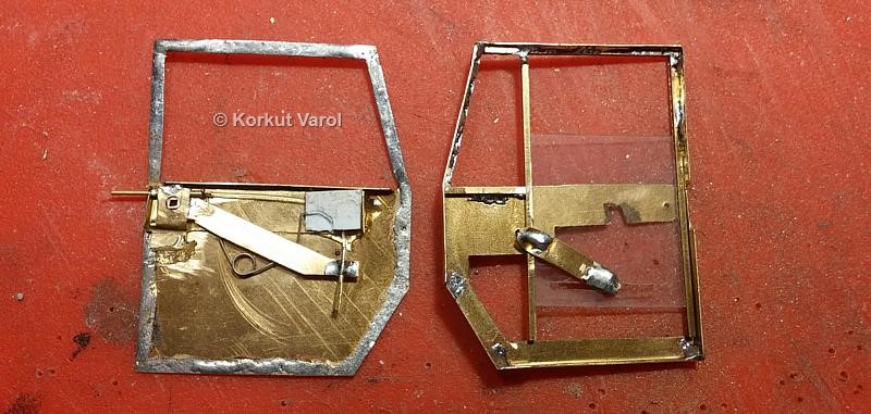
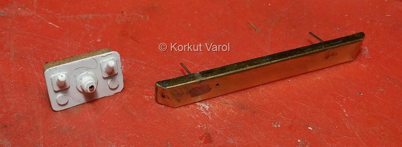
06 March 2016: I soldered the frame on the door
inner panel.
|
I carried on to the manufacturing of door hinges. Sequentially; 1- I cut a strip of brass and covered one side with a film of solder. This will be used for fixing the two sides after bending. 2- I bent the strip in the middle with the soldered side staying inside the bend. 3- I placed a pin inside the bend and formed a tube by squeezing with pliers. 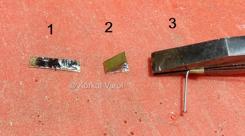
|
|
4- The bend turned out, naturally,
as a symmetric tube. However, the region mating the panel
should be flat.
5- To provide the flatness, I bent the part with pliers while the pin was inside. 6- The part was now asymmetric. 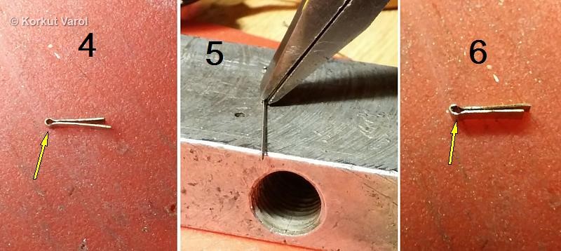
|
|
7- I pressed the tip of the soldering iron on the brass and melted the solder within. I removed the pin to prevent from being soldered together. 8- I refreshed the hole with 0.5 mm drill to clean out any residues from melting solder. 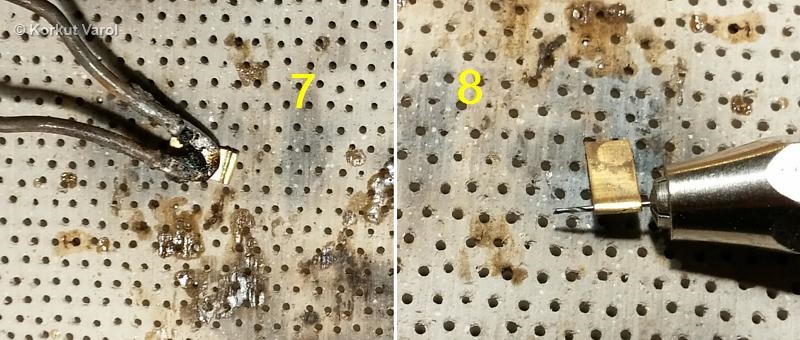
|
|
9- I took one part and with a Dremel, I opened a female groove for the counterpart. 10- I took the other part and opened a male section. 11- I joined the two parts and made a final check with the drill bit. 12- I cut off the excess parts from both sides and passed a 0.4 mm dia. copper wire through. A total of 4 hinges will wait like this until the time for assembling comes. 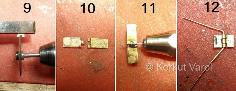
|
|
I joined the outer and inner parts of the
door with solder.
 |
|
08
March 2016:
I cut and
shaped the door surrounding panels of the cab.
|
|
11
March 2016:
Meanwhile, I
made the fascia panel
from brass sheet and the heater unit from styrene and chipboard. Both
units incorporate positioning wires at their back sides for correct
positioning within the cab.
 |
|
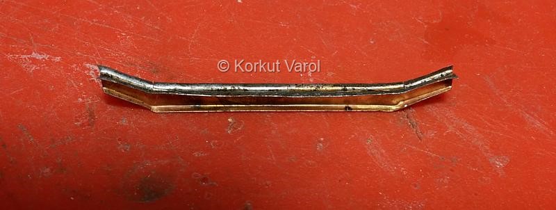
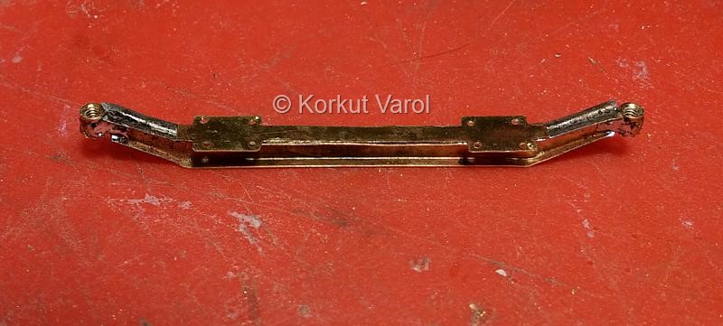
12
March 2016:
I went on to manufacturing of the front axle. I cut and
bent two symmetrical parts from 0.25 mm brass sheet to form the axle.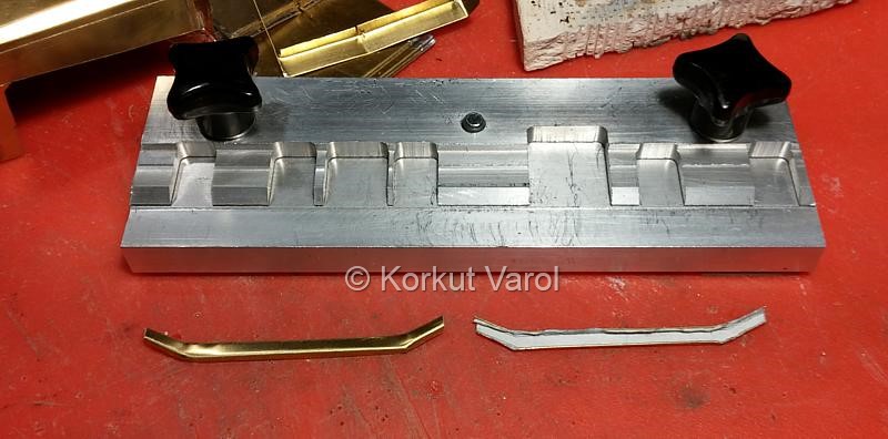
|
 |
 |
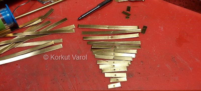
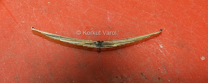
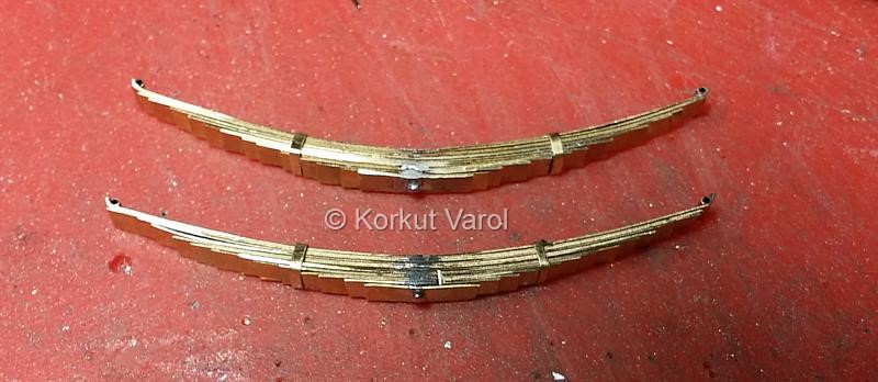
The design of the front leaf springs on Autocad. I determined the lengths of each leaf from this drawing. 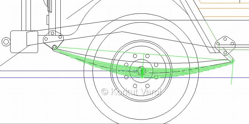
|
|
|
13 March 2016: 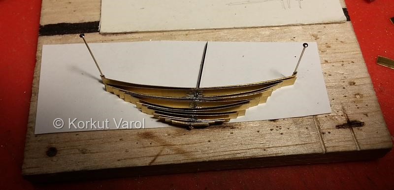 |
|
|
|
|
15 March 2016: 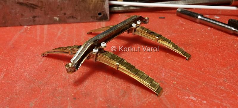
|
 ................. ................. ......... ......... |